


2D CAM Pocketing | VISI 2018 R2
Enhanced 2.5 Axis Pocketing strategy is available in within VISI 2018 R2 which does automatically create predrill hole features. Predrill hole features are generated both from the plunge point calculated by the system or from the point selected by the user. The plunging points position is optimized by the system to create just the minimum number of pre drill holes.

Toolpath mirroring | VISI 2018 R2
The new Mirror functionality allows the creation of a copy of the current project and to mirror all the toolpath operations contained within it. The “Mirroring” can be achieved on any 2 axis, 3 axis, 3+2 axis and 4/5 axis toolpaths generated in VISI. The mirroring, as extremely important, retains the original cutting direction for all the operations. The benefit is a time saving for the preparation of toolpaths on mirrored geometry, widely used on the automotive market.

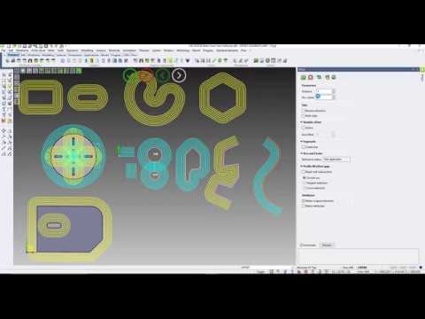
Boolean operations on profiles | VISI 2018 R2
It is now possible to achieve Boolean operations on Profiles such as unite, subtract, intersect which are often useful for both modelling and machining purposes. The new Boolean functionalities reduce the need to dissolve, trim and regenerate the desired profiles.
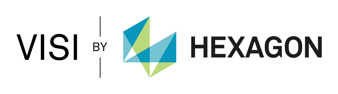
Reverse Engineering | VISI 2018 R2
The new Reverse module, which is completely integrated in the VISI product, allows to load a points cloud and to create the relative mesh by setting different options to refine and smooth it. It allows to load a point cloud either from a Romer Absolute Arm or from an external file and generate the desired and optimised mesh thanks to mesh tools available to refine it. The resultant mesh could be used to create the relative surfaces, by using the available modelling functionalities, or used as it is for machining porpoises.

Enhanced User Experience | VISI 2018 R2
The user experience on VISI 2018 R2 has been improved with the introduction of a more intuitive contextual toolbars. The new contextual toolbar on active selection allows to switch between the contextual functionalities accordingly to the geometry selected. The result is a more intuitive, simplified and rewarding user experience. The graphical sliders management has also been improved so that only slider labels for selected slider is shown on the screen.

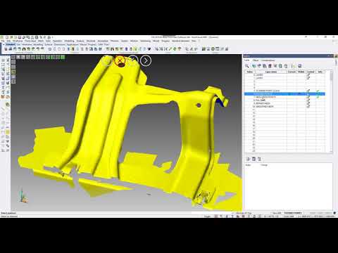
Assembly Management For Multi Cavity Moulds | VISI 2018 R2
The management for multi cavity moulds has been enhanced on 2018 R2 in order to simplify the insertion of standard components in within the inserts of the mould. When adding a standard component in a mould insert, a solid group will automatically be created in order to manage the component as part of the mould insert and any modification to the insert will be automatically propagated to the other inserts.
Matching Faces Selection | VISI 2018 R2
The face selection has been enhanced to allow matching faces to be selected. It is now possible to select matching faces by providing specific conditions such as faces types (planar, cylindrical, fillets), radius condition, faces orientation, colours and others to dynamically select similar faces accordingly to the conditions provided.

Filling Validation For Plastic Moulds | VISI 2018 R2
The Filling validation drives the user to run a flow analysis in advance of the tool design, in order to determine the most appropriate gate positioning. The analysis allows to predict and visualize how the part is filled by the plastic melt so to identify possible welding lines and air traps location, and to settle the injection pressure requirements
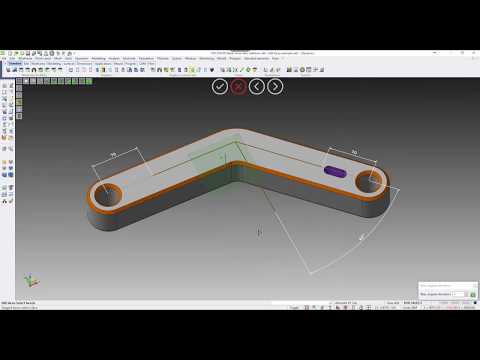
Enhanced Direct Modelling | VISI 2018 R2
The direct modelling capabilities have been enhanced further to provide more editing functionalities on both solids and surfaces. The new “Edit Face” functionality allows to achieve editing on solid bodies simply by moving or pulling the selected faces of a body, concentric faces can also be automatically selected and edited accordingly.

Dynamic Workplane Management | VISI 2018 R2
The new Dynamic workplane management provides greater flexibility and ease of use as the workplane gets dynamically and automatically orientated as soon as moving the selection on the desired face of a solid during any operation.

Enhanced Surfaces | VISI 2018 R2
The Auto Constrained surface can now be generated from curves with different number of elements (or edges) and the resultant surface quality has been widely improved. The Fill holes can now be generated from multiple edges of a body or by simply selecting a set of faces of a body to fill all the holes present on the selected faces.
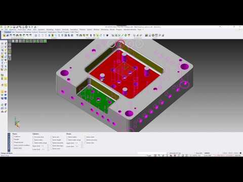
Enhanced Sketch | VISI 2018 R2
Sketching capabilities have been enhanced by providing a new Offset functionality which does support multi-selection and does allow to offset any geometry type. User interaction during the sketch creation has been improved by editable labels on the sketched geometry.

Progressive Die Design | VISI 2018 R2
A new graphical analysis (called Forming Limit Diagram) has been implemented to provide a map of the strain state of a sheet metal part in order to help the designer on the blanking result evaluation. Formability describes whether the part is safe or will have areas with a tendency to split or wrinkle in order to support the designer during the design phase of the die. The nesting now allows to compute the nesting on solid punches and the result of the nesting operation can be used for wire operations.