


Latest VISI Release Addresses Springback Puzzle
The latest release of VISI, Vero Software’s specialist mould and die solution, delivers a number of user experience enhancements and addresses an issue that is often neglected…but which can have an important effect on the final shape of a formed sheet metal component.
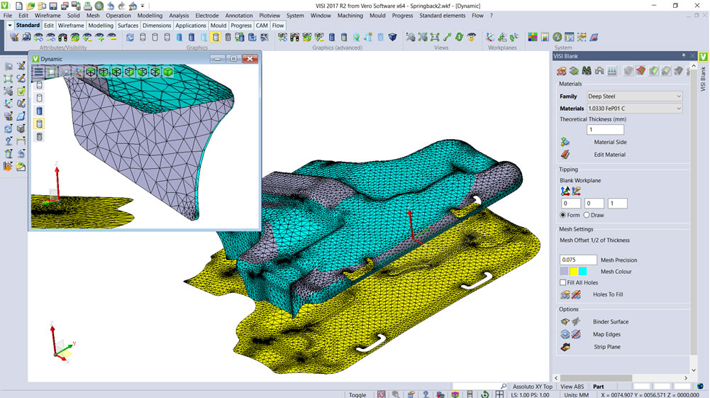
When the sheet metal part is removed from the die, and the forming forces released, material elasticity will cause the part geometry to experience springback. The new Springback prediction functionality in VISI 2017 R2 is designed to reduce the time and cost of a typical trial and error approach to solving this long-standing industry issue.
VISI Brand Manager Massimo Vergerio says: “Springback can make it difficult to control the part’s final dimensions. The new prediction tool starts from the nominal part, material data and blank calculation, generating a second mesh of the product’s geometry after springback. The designer can then achieve a morphing on the surface with the relative compensation tool, which generates the required compensated surface, producing the accurate die faces for the required sheet metal part.”
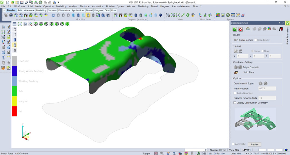
When a designer is validating the part for formability, a new graphical analysis representation mode will subdivide the results into six possible zones that occur during the forming process:
- Strong Wrinkle Tendency – slight stretch in one direction, and compensation in the other, with material thickening
- Wrinkling Tendency – stretch in one direction, and compression in the other, with slight material thickening, which may cause wrinkles to occur
- Low Strain – minimal stretch or compression in either the major or minor directions
- Safe – area below the Forming Limit Curve where failure is unlikely to occur
- Marginal – the area between the safe and fail zones, where the forming process is marginally safe
- Fail – the area above the Forming Limit Curve where splitting and localised thinning is likely to occur.
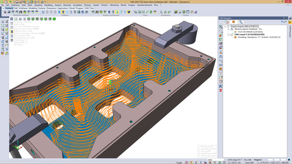
Amongst several items of new and enhanced functionality for both CAD and CAM processes, the new 2.5-Axis Pocketing Strategy in VISI 2017 R2 improves toolpath quality, optimises toolpaths on open features, and allows machining from a stock model. “When the stock model is defined, the new Pocketing Strategy can identify the areas where it’s necessary to remove the material and adapt the toolpath to produce passes only when they’re needed,” says Massimo Vergerio.
And he says high speed machining can now be achieved with the new 2.5-Axis Waveform Strategy (previously available in 3D roughing), which maintains constant tool cutting load, constant cutting feed rate, and a smooth toolpath which avoids sharp changes in direction.
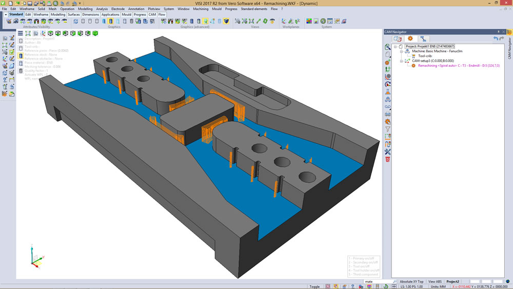
Based on the Pocketing technology, the new Remachining Strategy inherits the same enhancements and advantages. Rest area recognition is achieved automatically, based on the reference operations. A new residual stock algorithm is used for both 2D and 3D operations and the Dynamic Incremental Stock command. This will ensure a consistent toolpath quality regardless of the operation type.
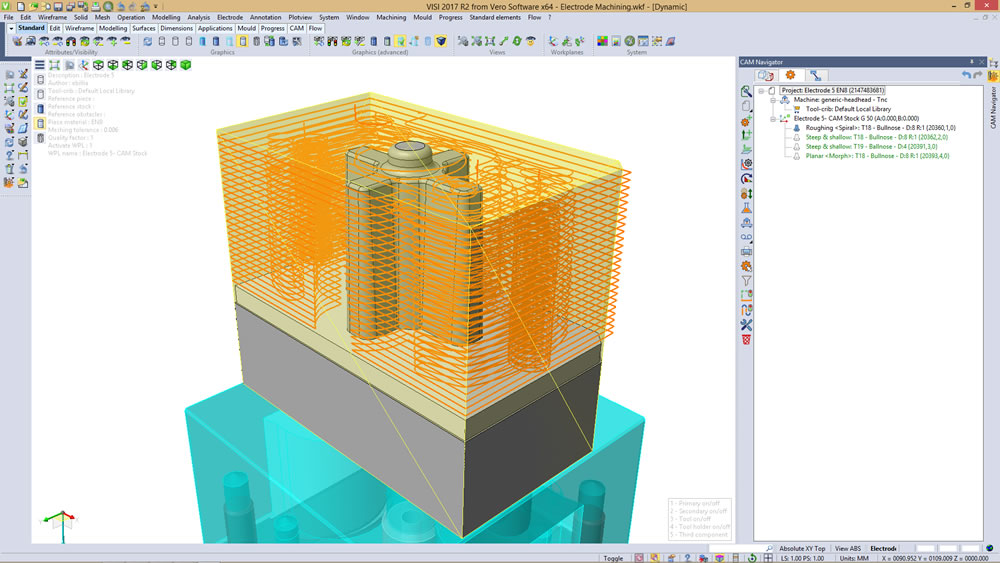
The new Electrode machining module automates the electrode design-to-manufacturing process. It benefits from all the relevant electrode data added by the operator during the electrode creation phase, while also removing the potential risk of possible input error. “That’s because this data doesn’t need to be added again for machining. Manufacturing data is collected during the design phase and automatically passed to the CAM cycles,” says Massimo Vergerio.
Where a substantial number of electrodes need to be machined, the new module automates the process, saving a considerable amount of time.
Briefly, other important enhancements introduced in VISI 2017 R2 include:
- New Product Launcher which is a customisable software starting window which provides access to the complete suite of installed VISI applications. The launcher also has dedicated areas for the users most commonly used tools which can be added by drag & drop, as well as displaying the VISI social media channels.
- Improved user experience with high quality toolbars to support 4k monitors.
- Improved Wire EDM technology and software fixes.
- Updated CAD translators to support the latest geometry formats.
CAD Import Interfaces (click to open)
| Import Format | File Extension | Supported Version |
|---|---|---|
| ACIS | .sat, .sab, .asat, .asab | R1 - 2017 1.0 |
| Catia V4 | .model, .exp | 4.1.9 - 4.2.4 |
| Catia V5 | .CATPart, .CATProduct | V5R8 - V5-6R2016 |
| Catia 3D Experience | .CATPart, .CATProduct | V62016x |
| STL | .stl | AP 203 |
| PLY | .ply | Various |
| DXF/DWG | .dxf, .dwg | 2016 |
| IGES | .igs, .iges | Up to 5.3 |
| STEP | .stp, .step | AP203, AP214, AP242 |
| VDA | .vda | 1.0 - 2.0 |
| Inventor | .ipt, .iam | V6 - 2017 (.iam V11) |
| NX (Unigraphics) | .prt | 11 - NX 10 (NX9 for PMI) |
| JT Open | .jt | V10.0 and older |
| Solid Edge | .par, .asm, .psm | V18 - ST9 |
| SolidWorks | .sldprt, .sldasm | 98 - 2017 |
| Parasolid | .x_b, .x_t, .xmt_bin, .xmt_txt | 1.0 - 29 |
| Creo (PTC) | .prt, .asm | 16 - Creo 3.0 |
CAD Export Interfaces (click to open)
| Writer Format | File Extension | Supported Version |
|---|---|---|
| 3D PDF | 1.7 | |
| ACIS | .sat, .sab, .asat, .asab | R18 - 2017 1.0 |
| Catia V5 | .CATPart, CATProduct | V5R15 - V5 R2016) |
| DXF/DWG | .dxf, .dwg | Various |
| STL | .stl | AP 203 |
| IGES | .igs, .iges | 5.3 |
| JT Open | .jt | Various |
| PARASOLID | .x_t, .x_b | Various |
| STEP | .stp, .step | AP203, AP214, AP242 (Geometry only) |
| VDA | .vda | 2.0 |